
TOOL MAKING
3D Digitizing in Tool and Moldmaking
Measuring Systems : ATOS TRITOP
Keywords: Tool try out, part shrinkage and spring back, duplication
The traditional method for the acquisition of measuring data is time-consuming and generally demands to transport the tool to the measuring setup or to the measuring machine. Today, powerful digitizing systems, based on the principle of fringe projection, are an integral part of industrial process and measuring chains and constitute a good alternative.
In tool and moldmaking it is important to capture the actual contour of a mold as well-fitting parts come from "wrong" molds which compensate shrinkage and springback of those parts during the production process and removal from the mold. In addition, the molds in production are subject to abrasion
During tool try-out and pilot production, the tools that were manufactured according to the CAD data are finalized by reworking. The complete digitizing of current tools and molds provide for defining the master. Based on this master, reworking of the tool is planned and carried out accordingly. In addition, a tool can be duplicated quickly without any problems.
Therefore, a powerful digitizing system should meet the following requirements:
Optical 3D Digitizing
The fringe projection sensor ATOS is based on the principle of triangulation. The sensor unit projects different fringe patterns onto the object to be measured. These patterns are then recorded by two cameras. Based on the optical image equations (calibration), the computer automatically calculates the 3D coordinates for each camera pixel of the scanned surfaces with high precision.
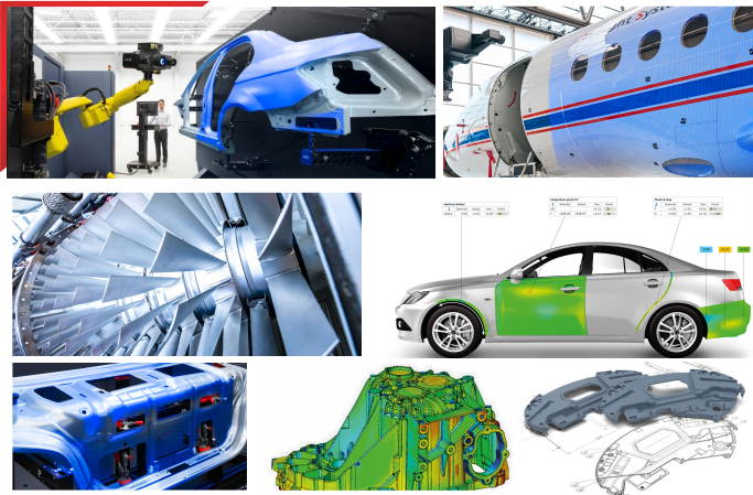
The mobile ATOS 3D optical digitizer can easily be adapted to special measuring tasks and object sizes in minutes by using different lenses. Thanks to this flexibility, the ATOS system is able to measure objects of various sizes, from filigree die-cast components to complete aircraft. When measuring larger and more complex objects, first reference point markers are applied to the object. In a second step, their coordinates are determined by means of the photogrammetry system TRITOP. These markers define the object's coordinate system.
Now, the ATOS sensor, mounted on a camera stand with the ability to be positioned flexibly in space, records the individual views and the positions of the reference points as digitized data.
When recording the views, ensure that in each scan at least three markers are visible in the stereo images of both cameras. The ATOS system records the 3D positions of the markers and the scanned data in the sensor's coordinate system. Then, the marker coordinates are transformed to match the mesh of the reference points that have been predefined by previous measurements or by photogrammetry. In a next step, the same transformation rule is applied to fit the digitized surface points in the object's coordinate system.
The ATOS system saves the relevant images and data of each measurement in a project. During each measurement, ATOS checks if the measuring system is decalibrated, the sensor moves or if any external events negatively affect the measurement. In addition, the software displays the deviations in measurement; thus, optimum data is always available to the user for checking all factors of influence.
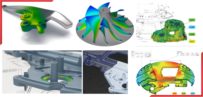
Quality Control
For quality control, the original master data can be superimposed on the measuring data of digitized parts. Based on such an "As Designed" vs. "As Built" comparison, the user may check whether the tolerances have been met or in which area the part is deformed. Figure 1 shows the digitizing of a tool. The goal was to compare the tool with its CAD model. Modifications during the try-out phase and production launch can be integrated into the CAD model using surface reconstruction.
Another field of application is the verification of the entire car body in pilot production. The vehicles of the preproduction series are verified with respect to the correct alignment of all car body parts.
The ATOS 3D digitizing system also provides for determining the position of so-called feature lines (component border lines, holes, design and tape lines). Based on this data, individual data points, geometric elements and component border lines can be extracted. The measured data and the CAD model are imported into the ATOS inspection module. After the alignment of the coordinate system (e.g. RPS registration), the deviation of individual points can be calculated and visualized (Figure 3).
A full color plot displays the distance between each measured surface point and the master. Now, the resulting deviation plot can easily be interpreted.
The deviation scale can be adjusted and adapted individually. A continuous color run legend correlates with the calculated deviations, however, the same legend can be displayed with discrete colors, or can be modified to a Go/No-Go scenario to show individual tolerances.
For documentation and further processing, reports can be created and the measuring results as well as the deviations may be exported in different formats (Excel, HTML, Word).
© 2022. APM Technologies 3D Pvt Ltd
Copyright © 2022. All rights reserved