COORDINATE MEASURING MACHINE
3D Digitizing of a Ford Focus Interior/Exterior Product Analysis
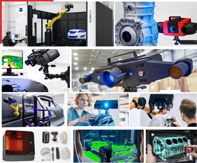
Measuring Systems : ATOS TRITOP
Keywords: Keywords: Virtual assembly, digital mock up
For the digitization, markers are put on the object. The 3d-coordinates of these markers are determined using a hand-held, high resolution digital camera and the XL software (based on photogrammetric techniques). With this software, the coordinate system of the measured data can also be transformed to match the coordinate system of the object. Then, individual areas of the model are digitized using the ATOS system.
In this case study, the interior, the exterior and the BIW (Body in White) of a Ford Focus have been digitized using the ATOS XL system. The measured data can be used in product analysis and "digital mock up" (DMU).
The digitization of a full size car is a standard task for automotive design studios. For this application, Coordinate Measuring Machines or Layout Machines were usually used. Since early in 1998, these systems can be replaced by ATOS XL, a white light scanner system.
In addition to the accurate and fast scanning of dense data points from the outside of the car, the ATOS system can also be used to scan the already built-in interior. This can be done in a standard car, due to the modern concept, the ease-of-use and the flexibility of the digitizing system. In this case, the measurement data of the interior and the exterior are lying in the same coordinate system.
For the digitization, markers are put on the object. The 3d-coordinates of these markers are determined using a hand-held, high resolution digital camera and the XL software (based on photogrammetric techniques). With this software, the coordinate system of the measured data can also be transformed to match the coordinate system of the object. Then, individual areas of the model are digitized using the ATOS system.
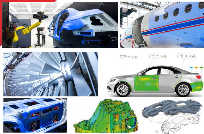
. For the digitization of the interior of the car, markers are placed on all parts which have to be digitized. Then the XL module is used to measure the 3d-positions of the visible markers and transform them into the coordinate system of the car. Elements which can be easily removed, such as seats, are put outside the car and digitized separately. The markers ensure that the coordinates of the removed components can be transformed correctly into the coordinate system of the car.
To digitize the inside of the car, the ATOS sensor is calibrated to a measuring area of typically 350 by 280 mm with short working distance, in order to have access to all needed views. For some details, the lenses of the ATOS system can be exchanged and the system can be calibrated for 200 by 160 or 100 by 80 mm working area. A professional studio stand with a long extension arm is usually used to move the sensor into the car through the door openings. By this means, the interior of the car is digitized in two days, including the floor, the ceiling, the dash board, the seats etc., with all the data in the coordinate system of the car.
Having removed the complete interior decoration, the front interior was digitized once more in order to gain the BIW (Body in White) form. Once again, photogrammetry was used to digitize the markers on the visible parts. In addition, the coordinate system was adapted to the already defined markers at the side panel and on the window pane. The newly visible area was then digitized with the ATOS system. Due to the fact that the BIW consisted of rather large areas and only the lower front and the floor had to be digitized, this task was finished within a few hours.
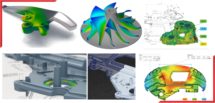
In an additional day, the complete data from the car was recomputed by the ATOS software into an STL file. Depending on the parameters, the ATOS software calculates the STL file with a regular grid structure or with a thinned-out structure, with low data density at flat areas and dense data points in areas with high curvature. This thinning allows the user to import the resulting data into standard software packages as the amount of data is reduced to a standard file size even for very big parts and cars.
Using these data, milling or modeling on STL data or Reverse Engineering jobs can be started. In addition, it is simple to duplicate the measured part using Rapid Prototyping Systems. By courtesy of Ford AG, Germany
© 2022. APM Technologies 3D Pvt Ltd
Copyright © 2022. All rights reserved