
PHOTOGRAMMETRY | RE OF CYLINDER HEAD
Reverse Engineering of a cylinderhead
Measuring Systems : ATOS TRITOP
Keywords: Casting, Reverse Engineering, Legacy Parts
Many old parts were conceptualized and designed when sophisticated CAD Software were not available. The designs were in the form of 2D drawings, templates and co-ordinate listings. Today for several reasons mentioned as under customers need 3D CAD models of these parts
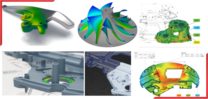
n all above application it is essential to faithfully capture all the features and recreate them in the CAD Model which should be a true representation of the part.
The process of Reverse Engineering is done in three main steps –
The accuracy of the process is highly dependent on the accuracy of the 3D-Scanning, therefore, a powerful digitizing system should meet the following requirements:
3D Whitelight Scanning
The fringe projection sensor ATOS is based on the principle of triangulation. The sensor unit projects different fringe patterns onto the object to be measured. These patterns are then recorded by two cameras. Based on the optical image equations (calibration), the computer automatically calculates the 3D coordinates for each camera pixel of the scanned surfaces with high precision.
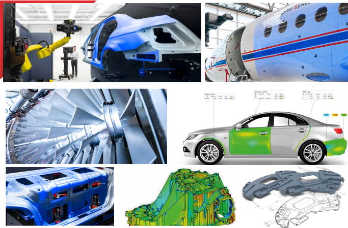
The mobile ATOS 3D optical digitizer can easily be adapted to special measuring tasks and object sizes in minutes by using different lenses. Thanks to this flexibility, the ATOS system is able to measure objects of various sizes, from filigree die-cast components to complete aircraft.
hen measuring larger and more complex objects, first reference point markers are applied to the object. In a second step, their coordinates are determined by means of the photogrammetry system TRITOP. These markers define the object's coordinate system.
Now, the ATOS sensor, mounted on a camera stand with the ability to be positioned flexibly in space, records the individual views and the positions of the reference points as digitized data.
When recording the views, ensure that in each scan at least three markers are visible in the stereo images of both cameras. The ATOS system records the 3D positions of the markers and the scanned data in the sensor's coordinate system. Then, the marker coordinates are transformed to match the mesh of the reference points that have been predefined by previous measurements or by photogrammetry. In a next step, the same transformation rule is applied to fit the digitized surface points in the object's coordinate system.
The ATOS system saves the relevant images and data of each measurement in a project. During each measurement, ATOS checks if the measuring system is decalibrated, the sensor moves or if any external events negatively affect the measurement. In addition, the software displays the deviations in measurement; thus, optimum data is always available to the user for checking all factors of influence.
© 2022. APM Technologies 3D Pvt Ltd
Copyright © 2022. All rights reserved